Intro
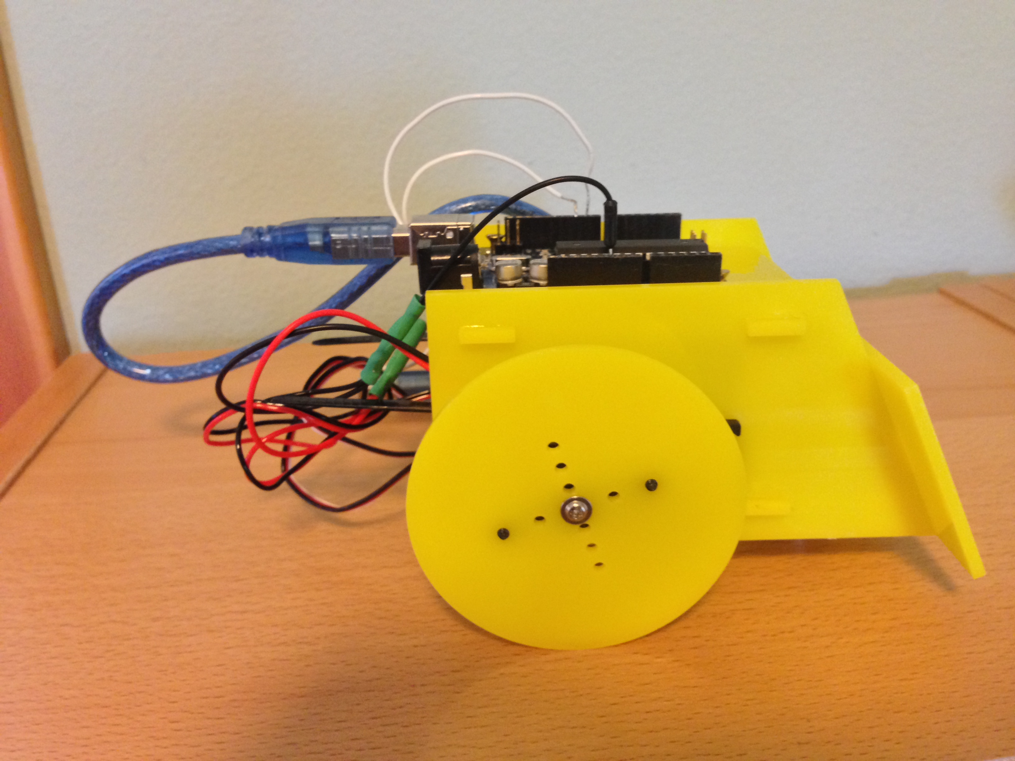
These instructions will help you build a Sumobot Jr. Here are some photos of a completed bot. (This bot is slightly different from the one in the construction photos - it's cut from acrylic and has soldered leads from the motors.)
Installs
- Git! https://help.github.com/articles/set-up-git#platform-all
- Node! http://nodejs.org/download/
- Update NPM if you haven't recently:
npm install -g npm@latest
- Update NPM if you haven't recently:
- Arduino software! http://arduino.cc/en/main/software
- Johnny Five
- Sumobot
Hardware
Tips:
- You don't need to spend lots of money prototyping. Use cardboard, coroplast (lawn signs), Popsicle sticks and duct tape.
- Use a medium to large screwdriver with a nice grip for more torque. (Those servo horns will be tough with a pen-sized screwdriver.)
- Protect your work surface and add a bit of grip by working on cardboard or a rubber mat.
- Sumobot Jr
- LaserCut and 3D patterns from https://github.com/makenai/sumobot-jr
- Other parts from https://github.com/makenai/sumobot-jr#other-parts-needed
- Assembly video http://sumobotkit.com/
- 6x #4 x 1/4" wood screws - 2 for each wheel and 2 for the ball caster. Wider threads are self tapping.
- The 3rd wheel: commonly a ball bearing; I've used a marble. But you could use anything wheel-like - such as a Lego wheel. You'll have to 3d print that ball bearing holder, or purchase some ball casters from the hardware store.
- Use wood if you can. Acrylic is shiny, but prone to cracking; cardboard is great for prototyping, but not so sturdy. Wood provides a nice balance between foundation and hackability.
Construction
-
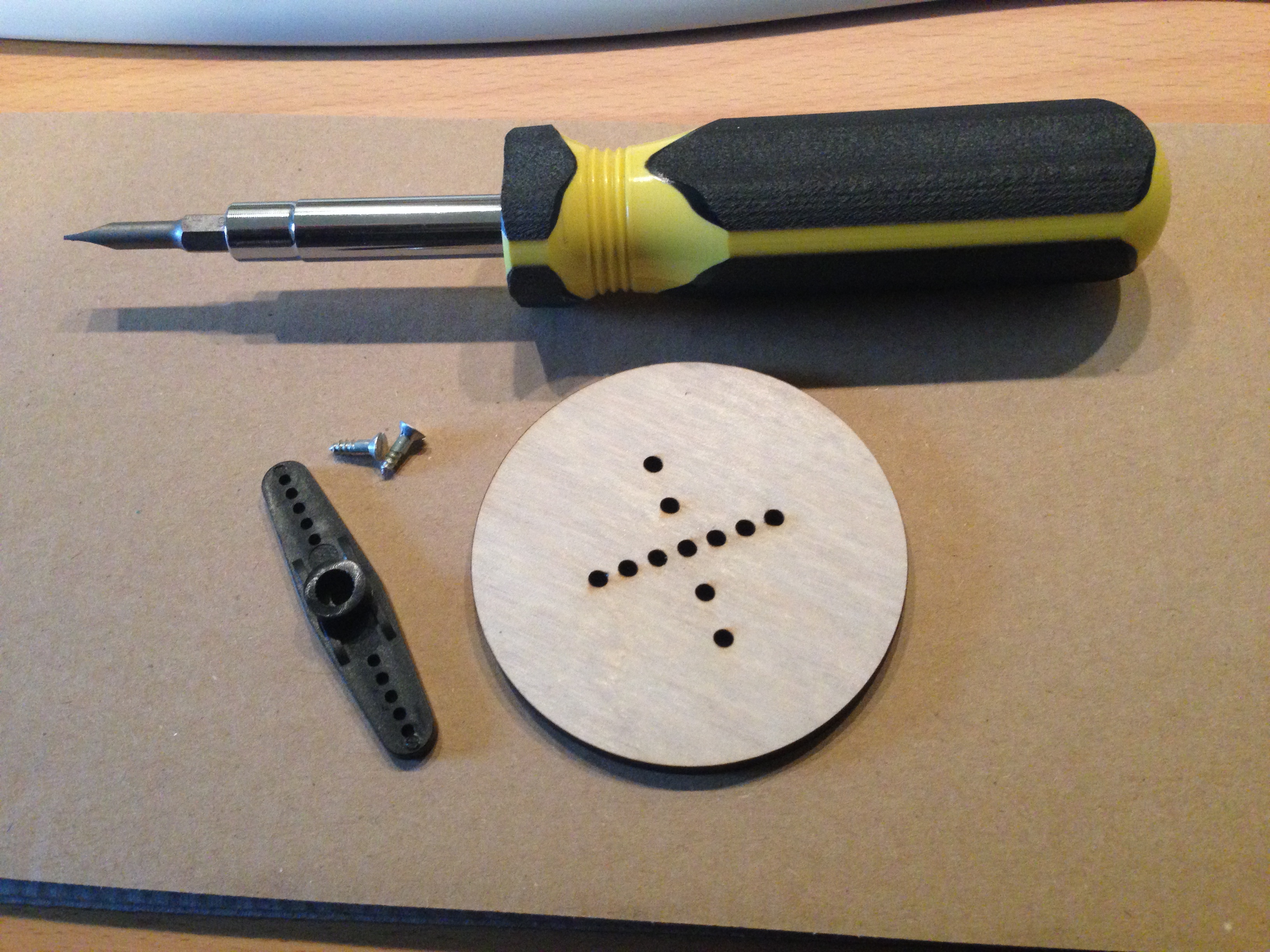
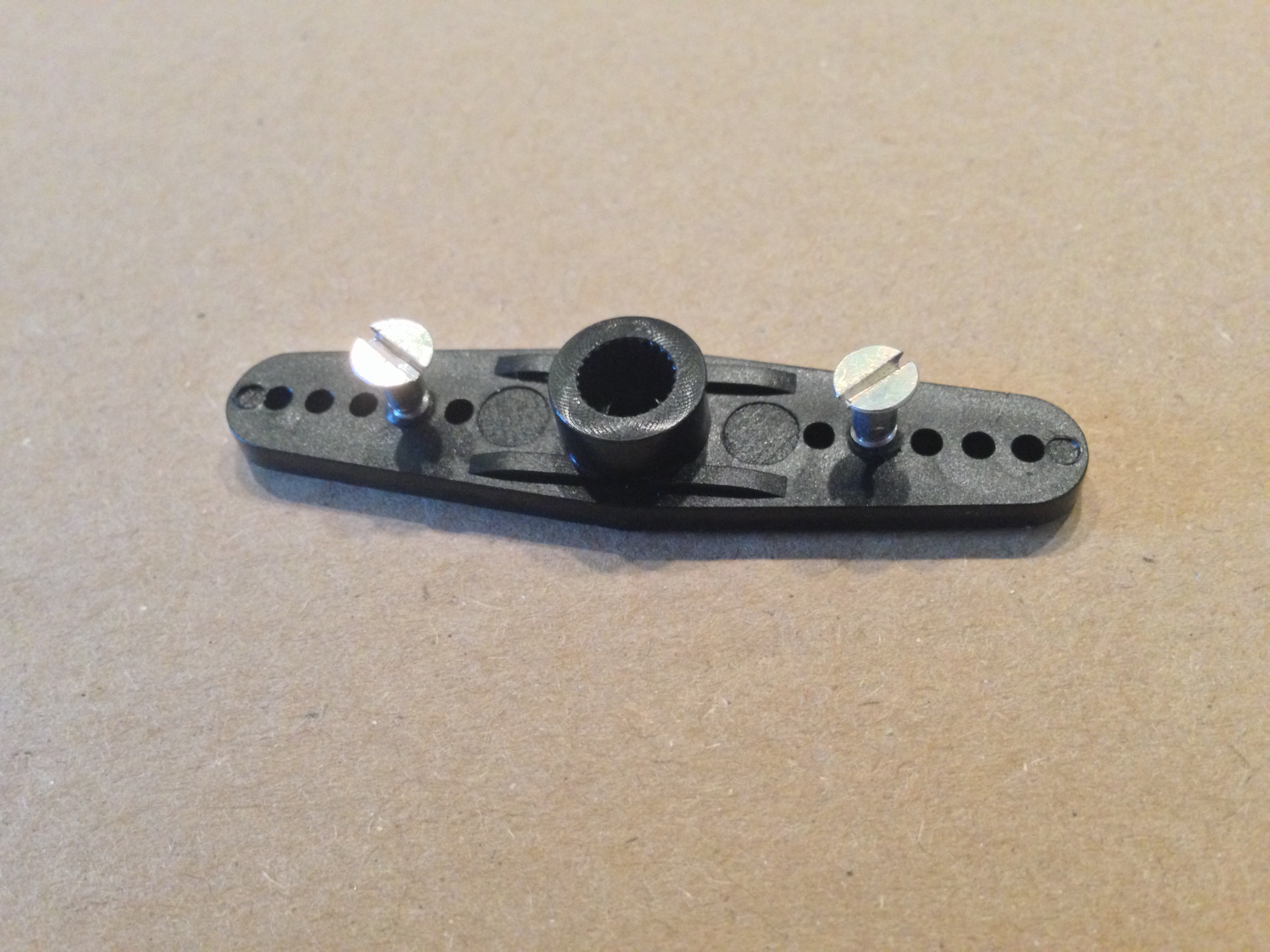
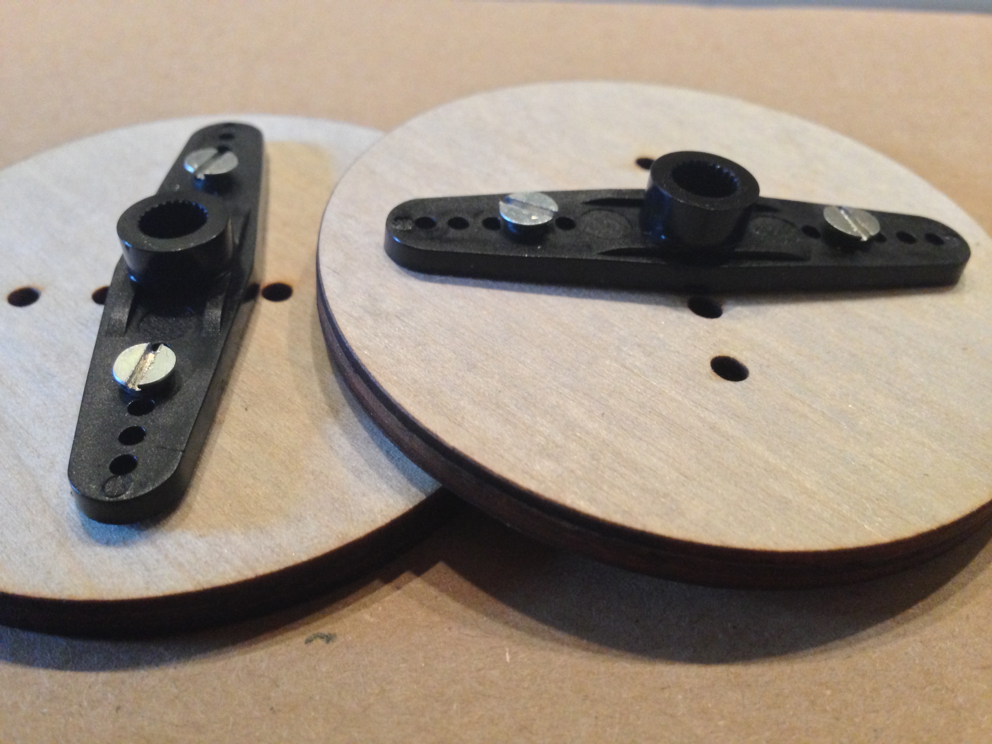
Start with 2 screws, a "horn" from the servo bag, and a Sumobot wheel.
-
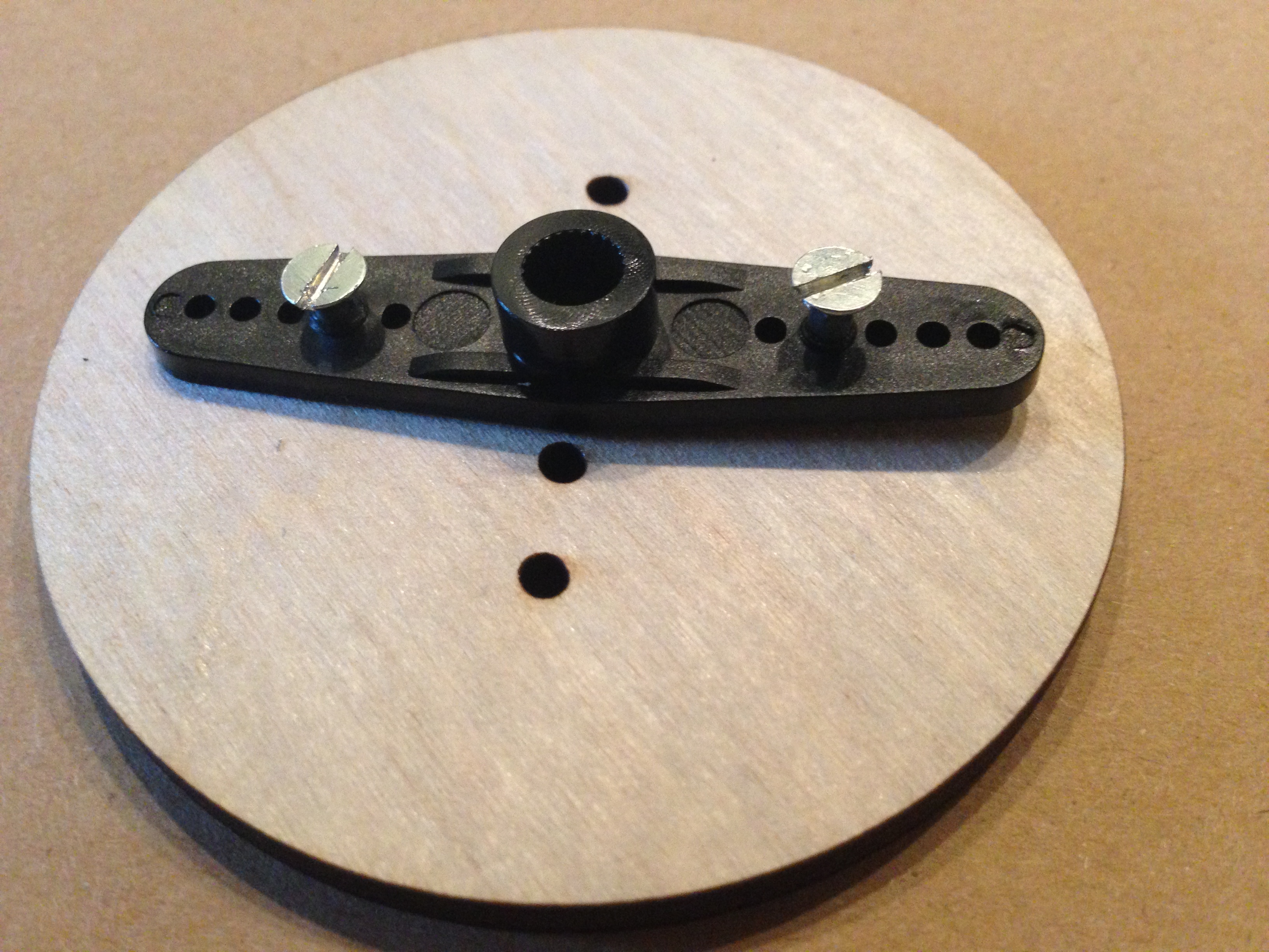
Check the alignment of holes in the your servo horns to the hole in your wheels. Be sure to screw into holes that will line up later.
-
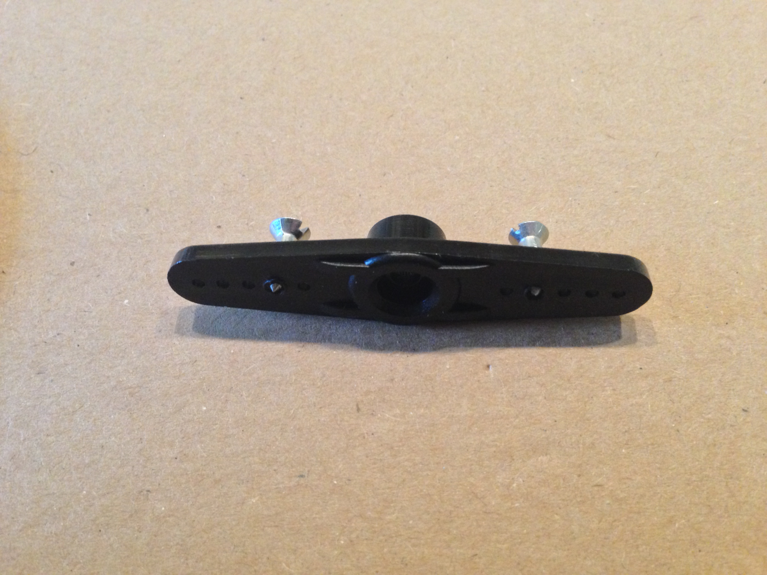
Screw one screw into each side of the servo horns. Don't be afraid to muscle them in there; you're drilling the threads as you go.
-
Drill until the screws' tips just come out the flat side of the horn.
-
Use the tips of the screws to line up to holes on the wheel. While pressing the horn towards the wheel, screw until tight.
-
Alternate which screw you're working on every so often to keep it even.
-
Make a second wheel and horn.
-
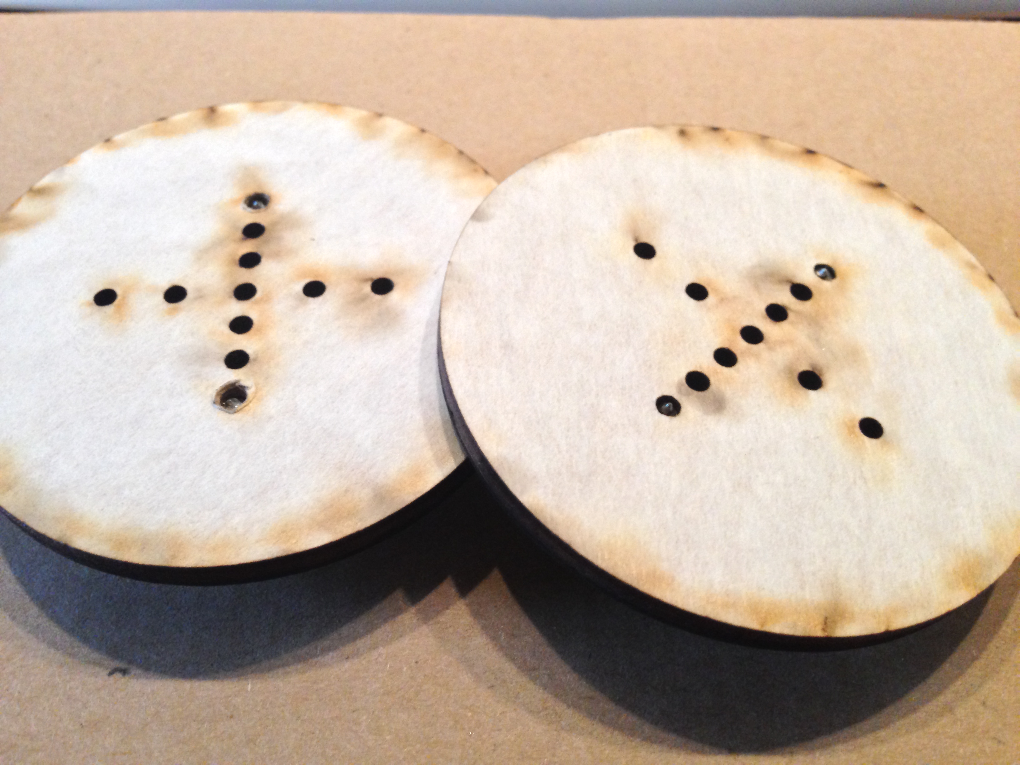
It's normal for the tips of the screws to stick out the back of the wheel just a little.
-
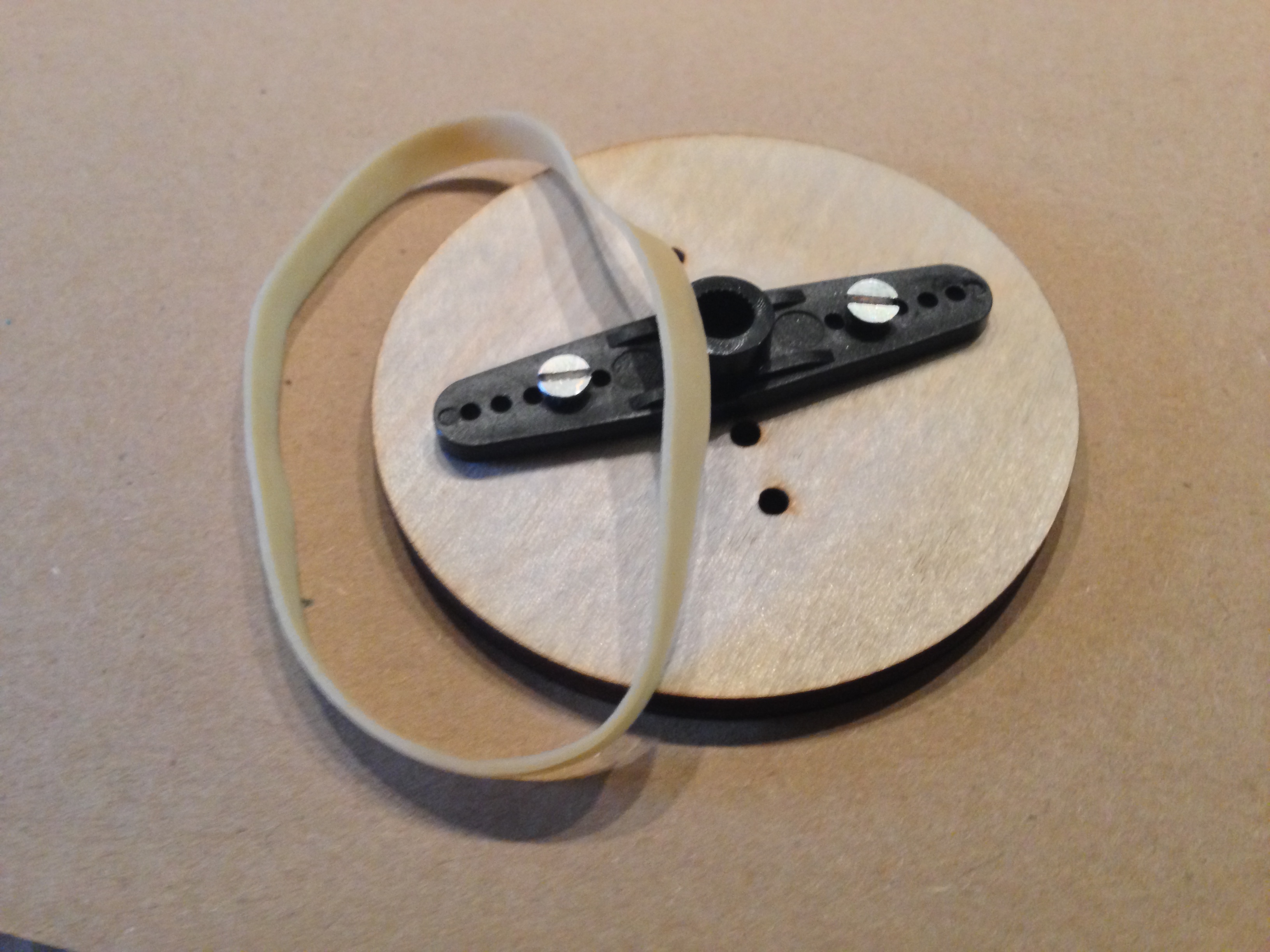
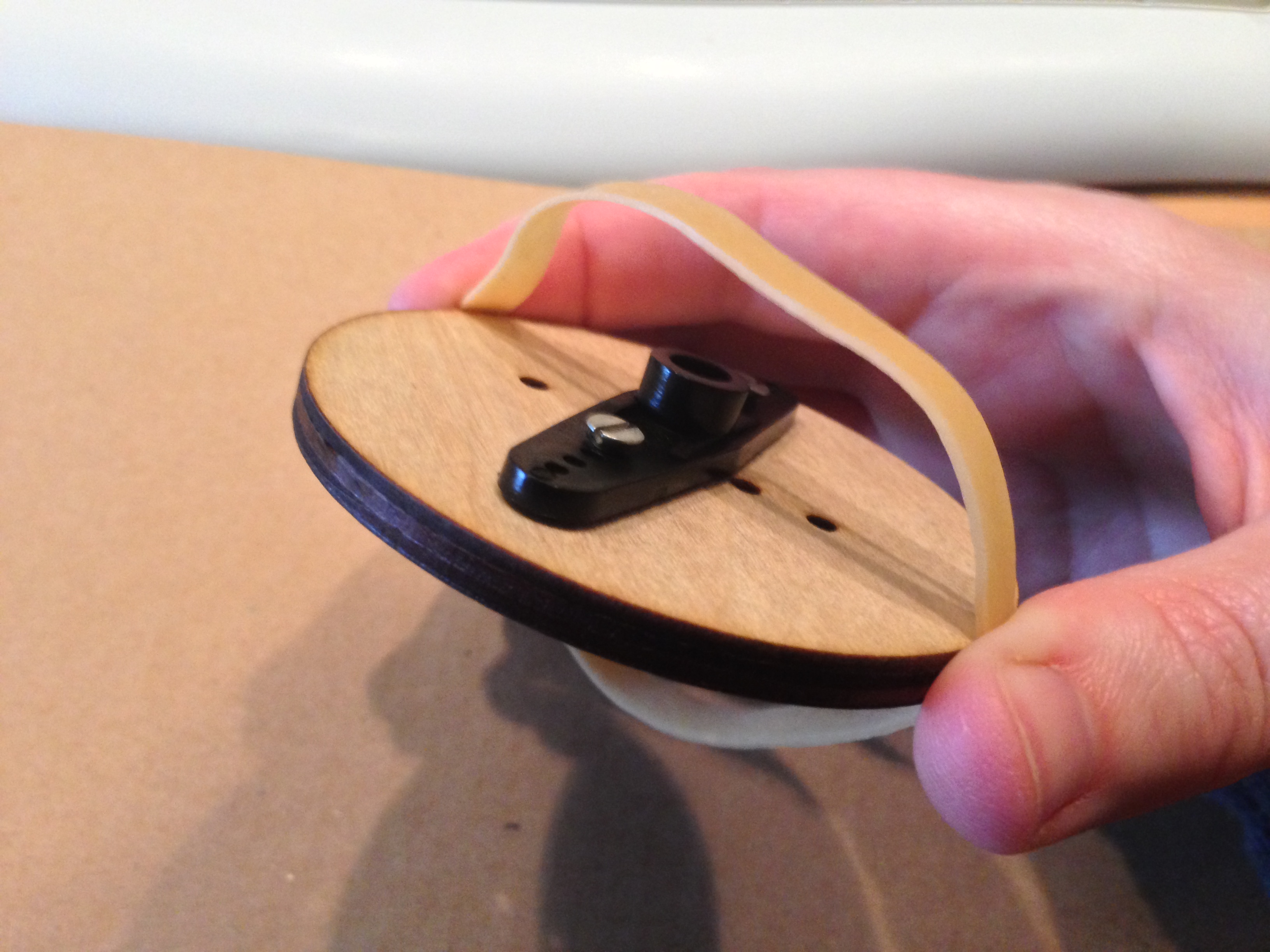
Get the traction-enhancing rubber bands for the wheels.
-
Use the band to circle the wheel perpendicularly.
-
Then rotate the band onto the wheel and coax in into place.
-
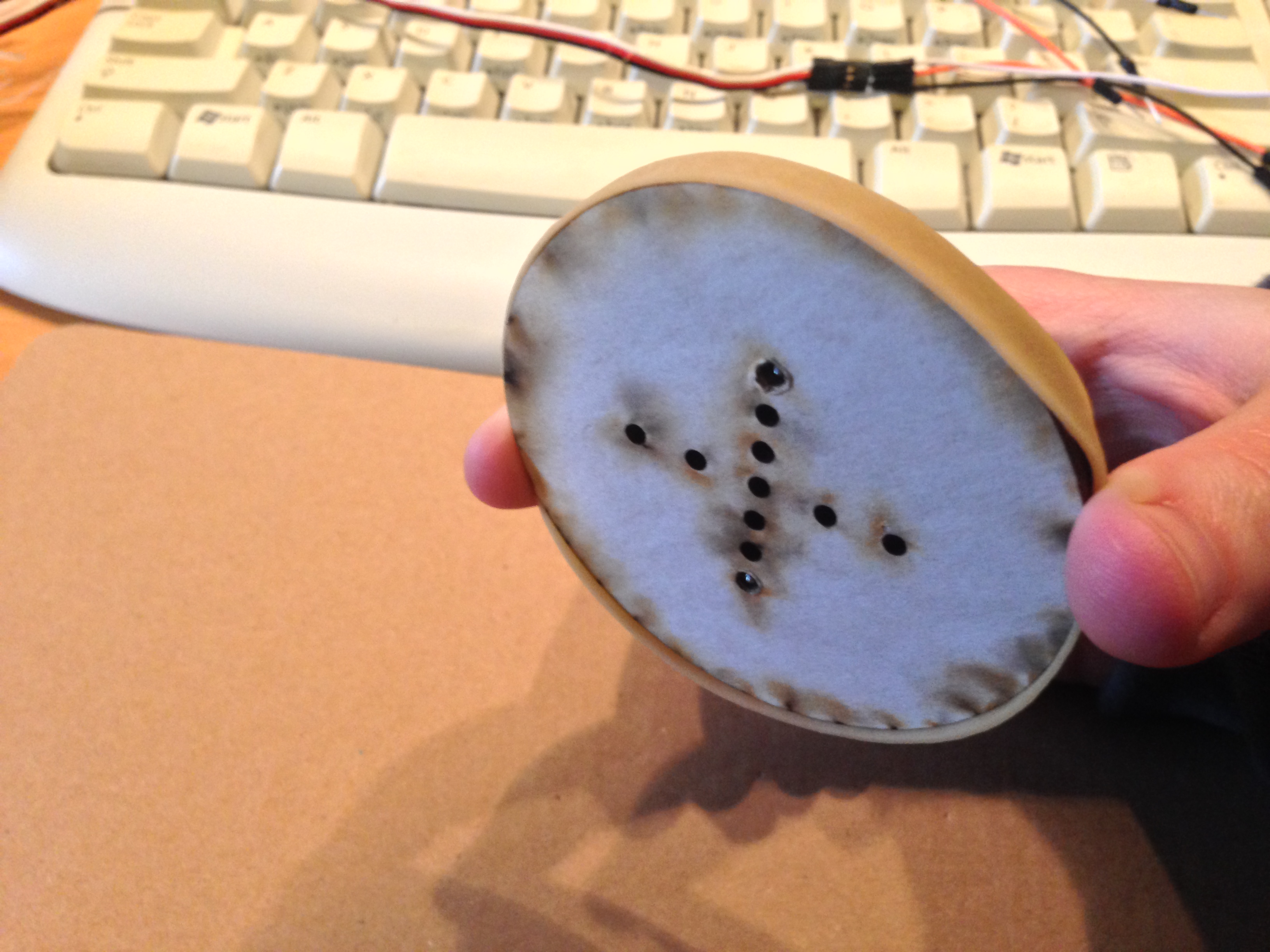
(On laser cut pieces, arrows point towards the front of the bot.)
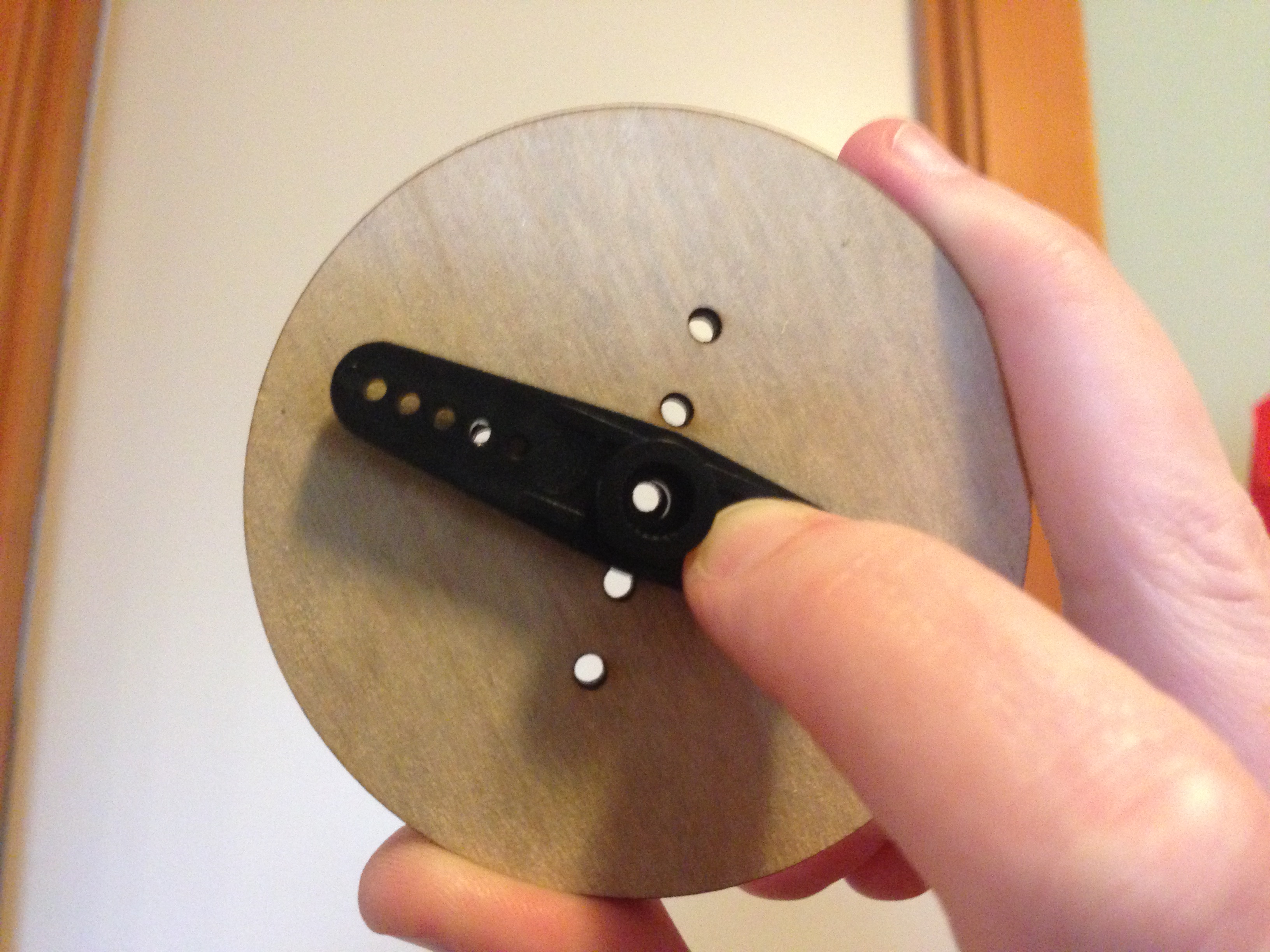
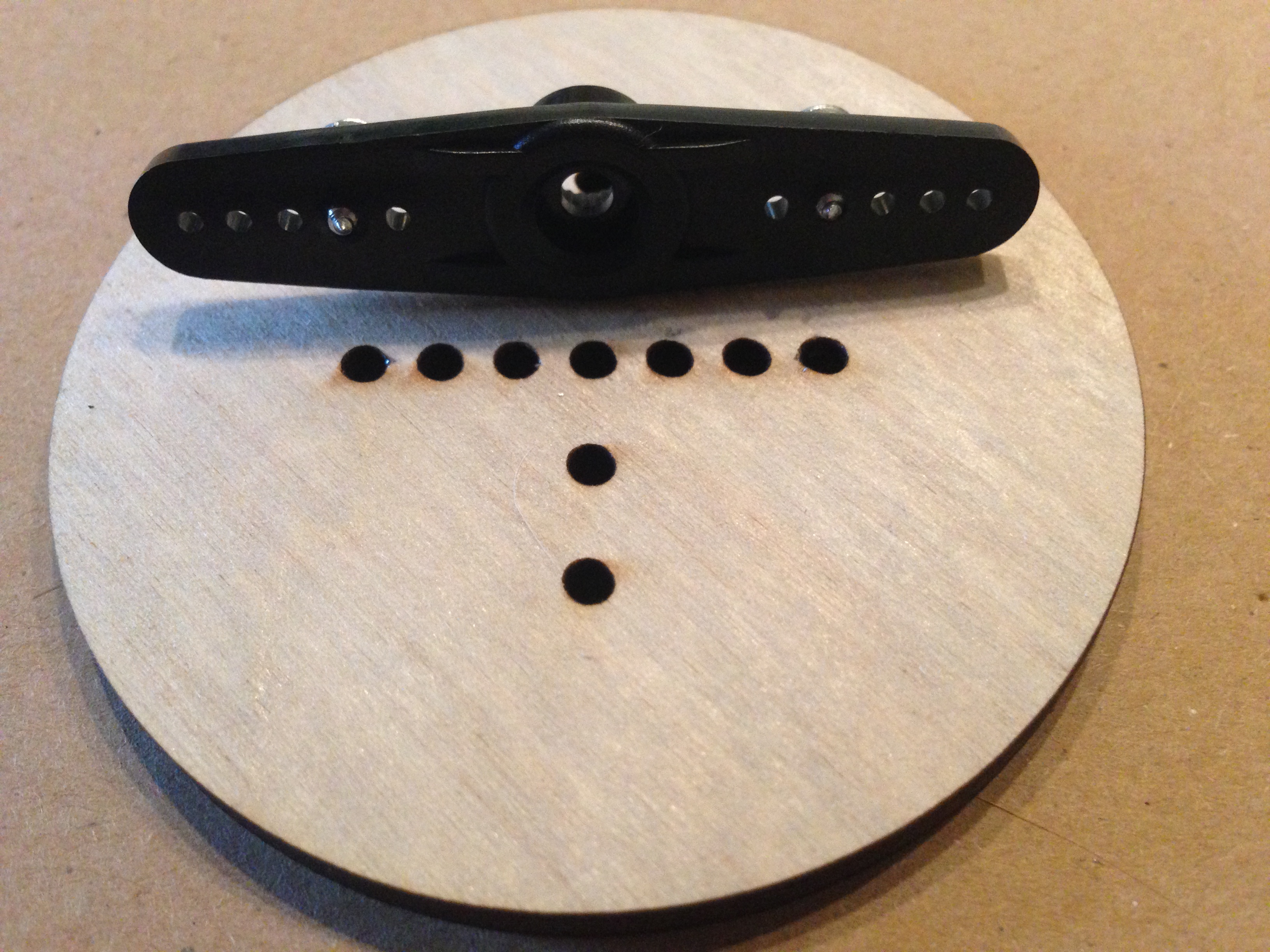
The bottom of the bot chassis is the largest of the rectangular pieces. Note that it has 2 circular holes near the front.
The sides are the 2 pieces with large rectangular cutouts and one slanted side towards the front.
The top of the chassis is the smaller one with 4 circular holes in it; the weird off-grid hole is the front.
The front of the chassis (aka the shovel) is rectangular with just two rectangular holes in it.
Slide the bottom piece into one of the sides, making sure the front and back edges line up.
Insert the top into one the first side piece, then slide the final side on.
Slide the front piece onto the front.
At this point, you can glue (Elmers, wood glue, super glue) and clamp the pieces together and let them sit for a while, or you can keep going unglued. Just don't keep working with wet glue.
-
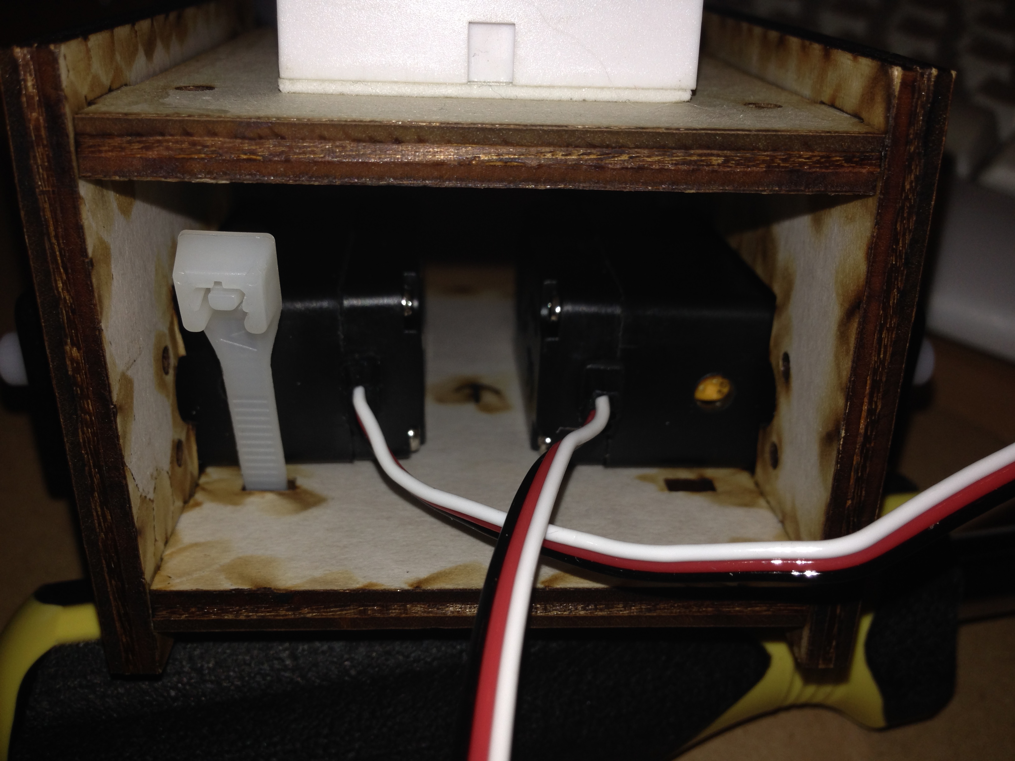
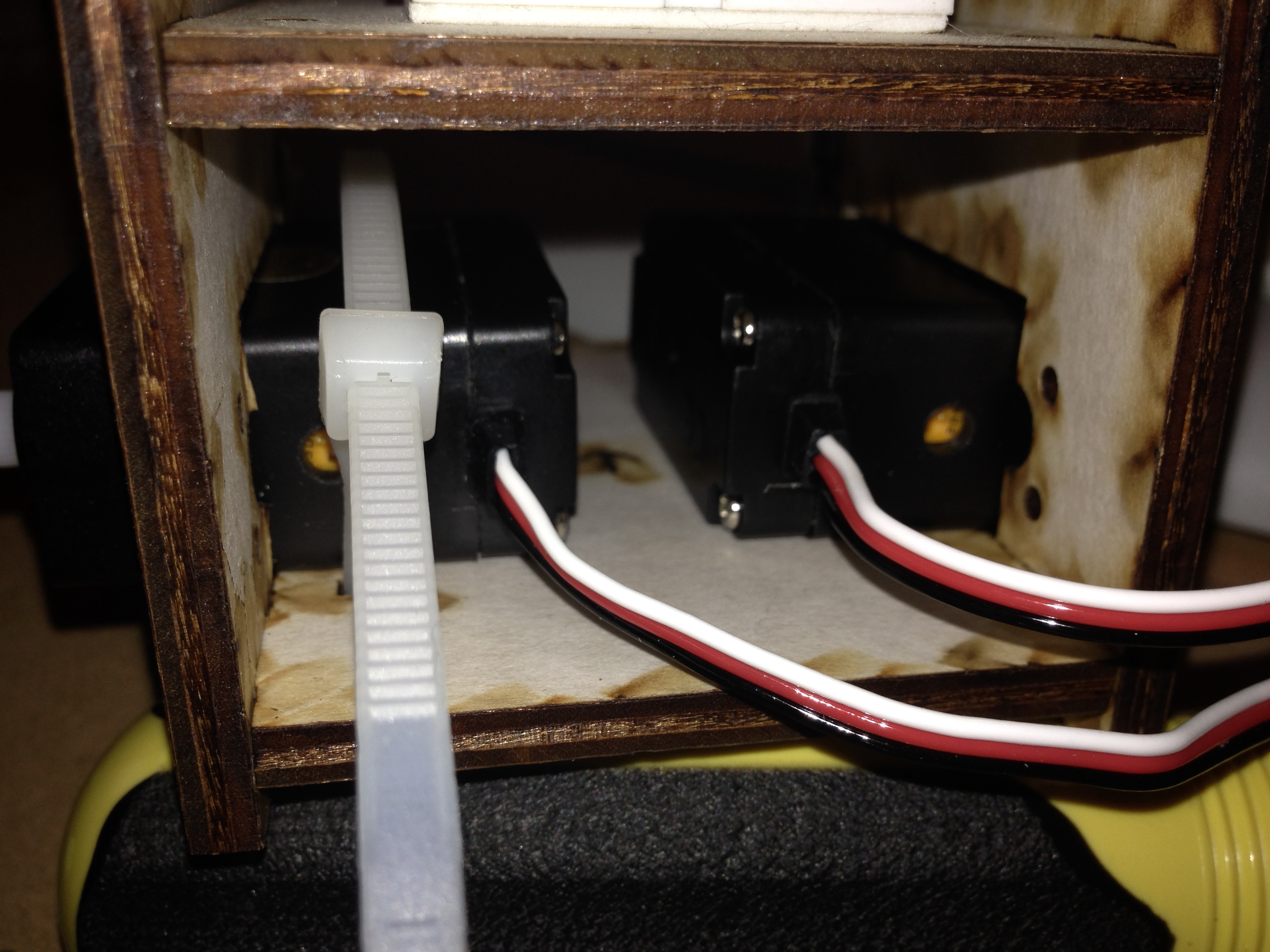
Insert the two servos into the chassis box, so that their posts stick out the sides of the bot. Insert the zipties into the holes just behind the servos so that their locktabs point backwards.
-
Wind the zipties back up through the bottom of the chassis, around the servos, and back through the locktabs. Tighten them. Now their tails stick out the back of the bot along with the servo wires. (Think about how you can decorate these when your bot is done.)
-
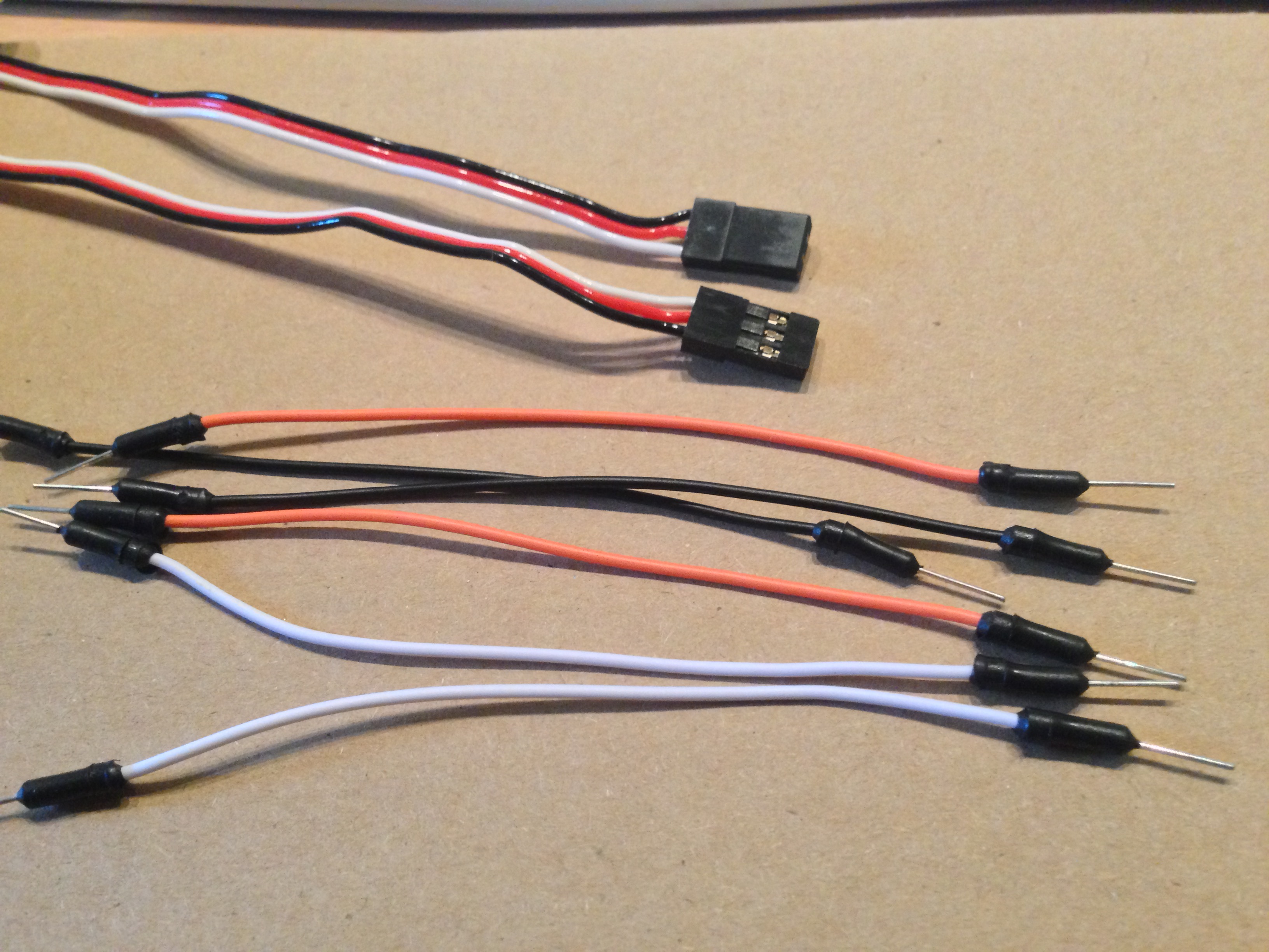
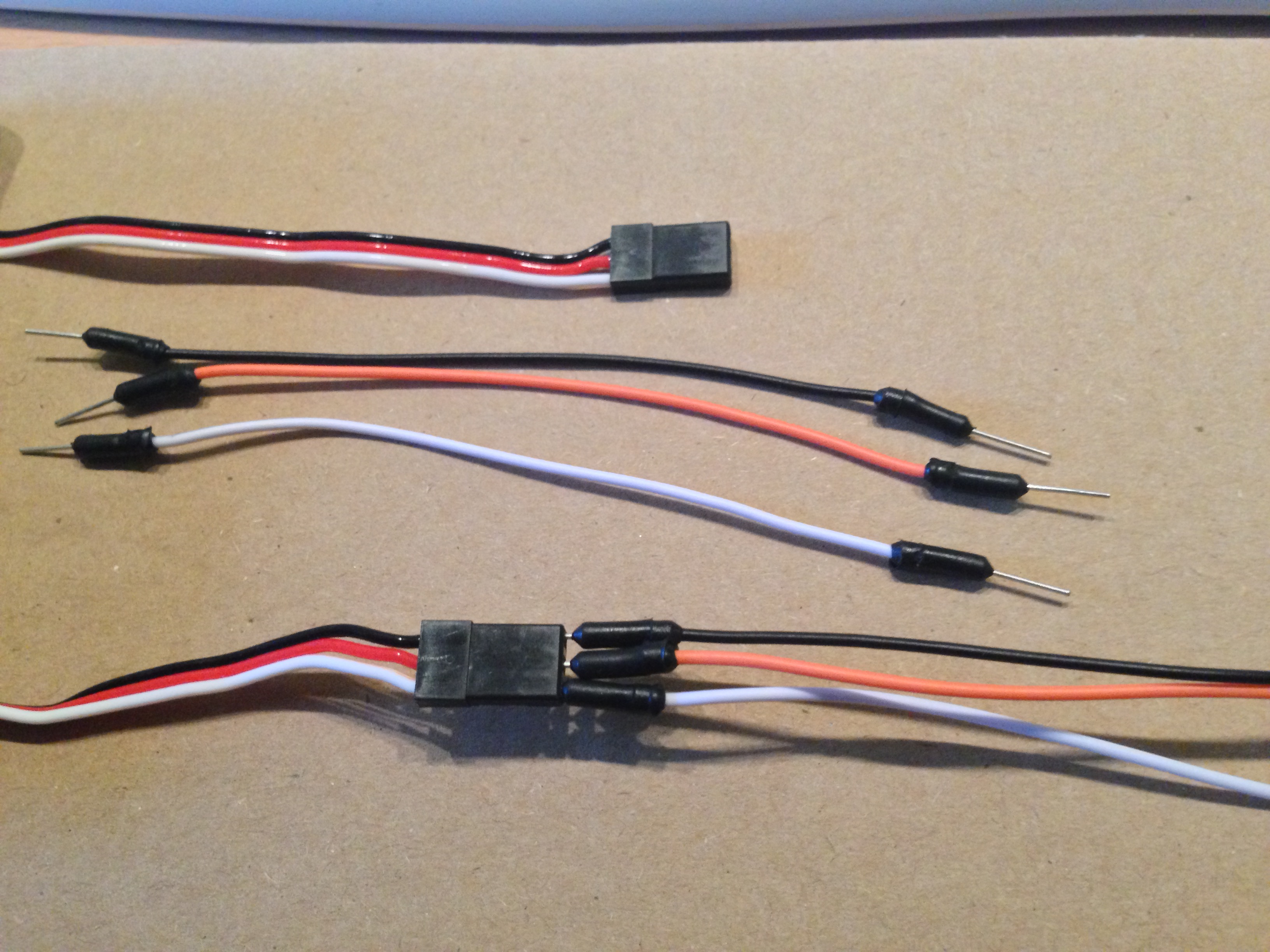
Instead of cutting wires and soldering, we'll use jumper wires to connect the servos to the Arduino board. Get 6 small to medium jumper wires; 2 each of white, black and red is a nice convention, but all wires work the same. I was out of red wires, so I used orange ones.
- Put the breadboard onto your sumobot.
-
Plug the jumper wires into the the connectors on the servos: white to white, black to black, and red to red (orange).
-
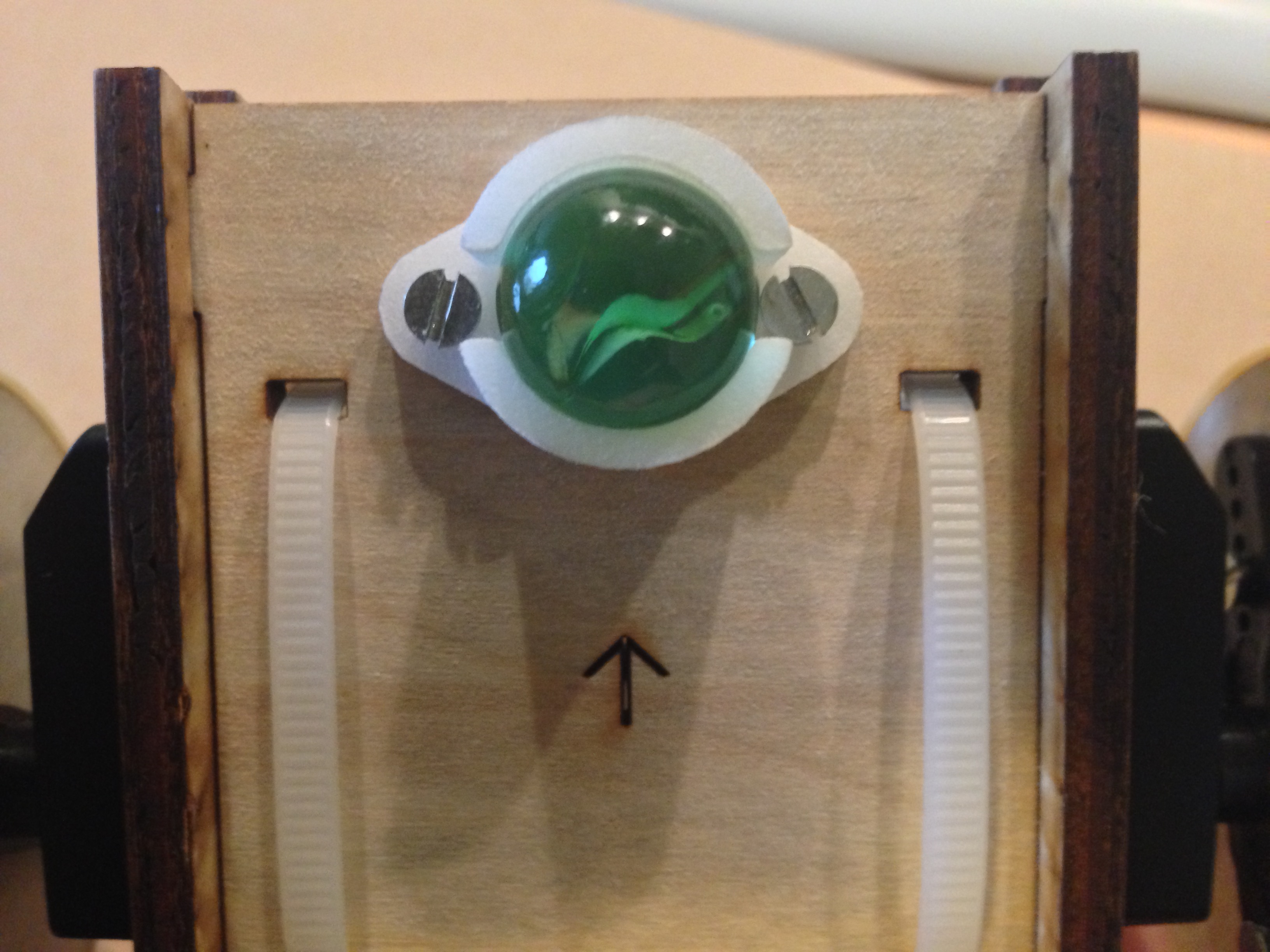
Screw the ball-bearing holder into the bottom of the bot, into the holes near the front. Put a ball bearing into the holder; I used a marble here.
- Put batteries into the holder, and slide the battery holder into the back of the bot, with the wires hanging out.
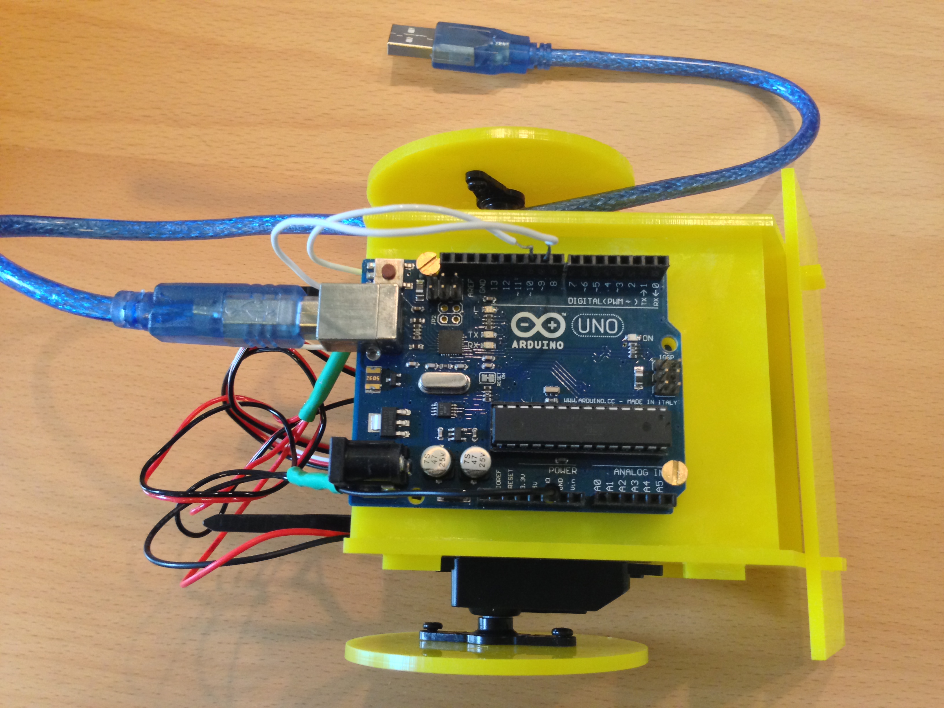
- Screw the Arduino board onto the top of the bot.
-
Using jumper wires if needed, connect the battery pack's red lead to +5 volts (probably pin 9) on the Arduino. Connect the battery pack's black lead to 0/Grnd on the Ardiuno.
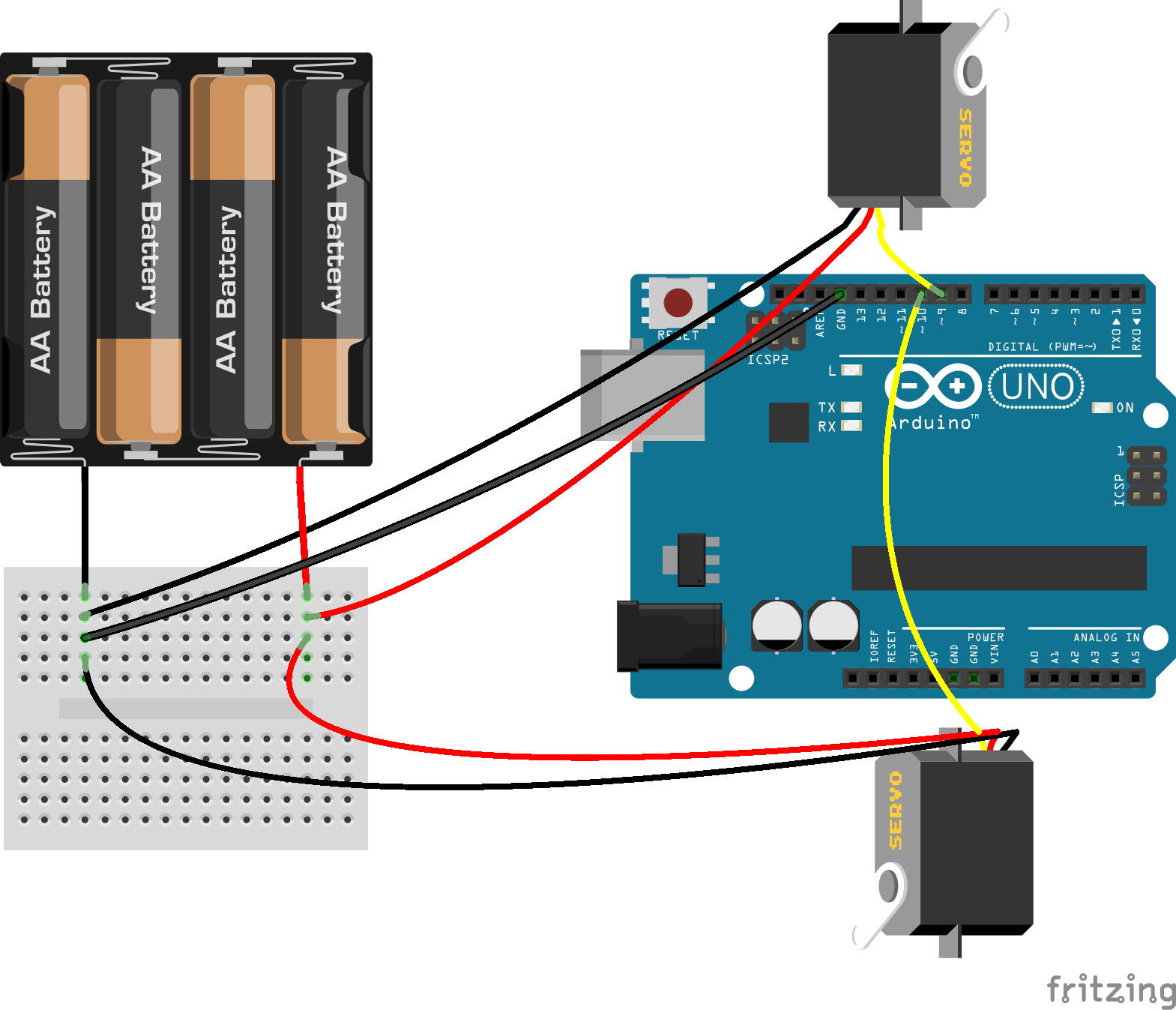
- For each servo, connect it to power (red), ground (black), and send the signal (white) to pins 10 and 11.
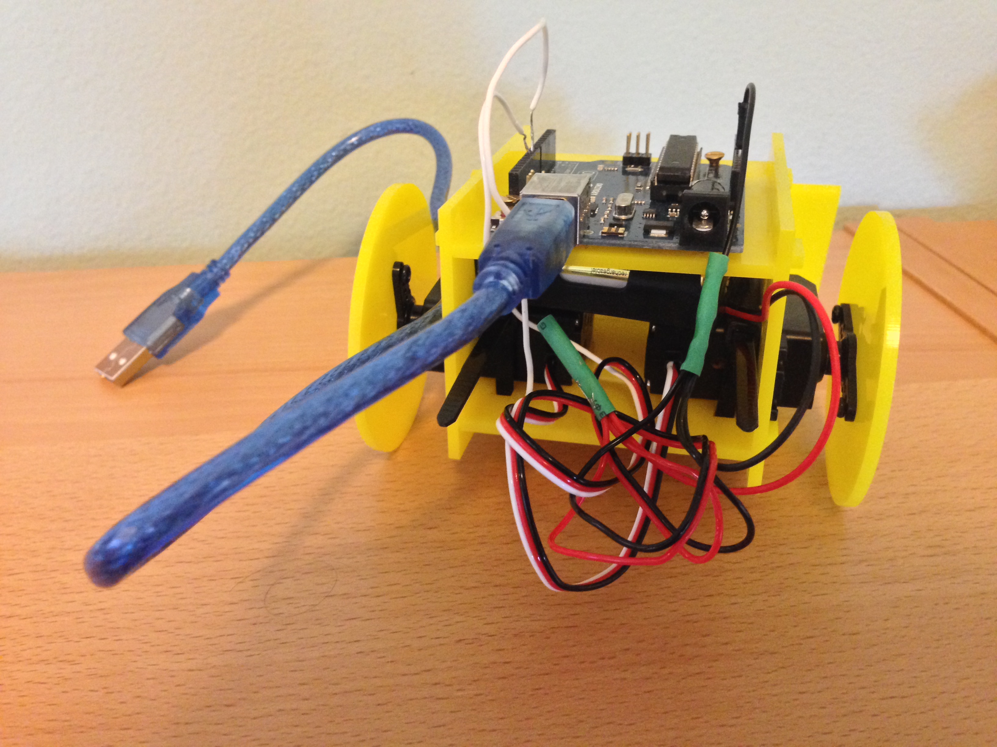
- Snap the wheels onto the bot.
- Give yourself a high-five - construction is done!
It's Go Time.
- Plug the Arduino into your computer via USB.
- The bot should be powered on and waiting for instructions from the computer. If the wheels are moving, adjust the small dials on the back of the servos until they stop.
- Run the Sumobot software and use your arrow keys to control it.
More About Sumobot Jr
- http://bocoup.com/weblog/customizing-the-robotsconf-sumobot-with-johnny-five/
- LaserCut / 3D patterns: https://github.com/makenai/sumobot-jr
- Other parts: https://github.com/makenai/sumobot-jr#other-parts-needed
- Assembly video http://sumobotkit.com/
- Battery holder: http://www.pololu.com/product/1153
- 2x servo motors: http://www.pololu.com/product/536
- Alternate parts list: http://briangenisio.com/software/2014/08/25/building-your-nodebot.html
- Nodebots Day in Melbourne: http://www.bossable.com/203/its-nodebotsday/
More Bots
-
Simplebot
- Cut plans and code from GitHub: https://github.com/nodebotsau/simplebot
- Assembly video: https://www.youtube.com/watch?v=KoACCjtkHIg
- Scout Patterns on Thingiverse: http://www.thingiverse.com/thing:13042
- Miniskybot (3D printable chassis): https://github.com/Obijuan/Miniskybot
- Hack-E-Bot (Open source robot framework for schools):
- Wall Avoiding Robot: http://www.instructables.com/id/Make-a-wall-avoiding-Robot!/?ALLSTEPS
- Hexy - open source hexapod: https://github.com/ArcBotics/Hexy
- Kitty Paparazzo - Sumobot chassis hacked to tack pictures of cats: https://github.com/lynnaloo/kitty-paparazzi/issues/1
- Mirobot - laser cut and make a robot: http://mirobot.io/build/fabricate/
- Aerogel - A node.js control library for the Crazyflie nano-copter: https://github.com/ceejbot/aerogel
- Batbot - Sonar-driven bag-escaping robot: https://github.com/rockbot/batbot